Xiaomi Redmi Note 7 (xiaomi-lavender)
Status: Boots and has USB, framebuffer and touch
 Redmi Note 7 | |
| Manufacturer | Xiaomi |
|---|---|
| Name | Redmi Note 7 |
| Codename | xiaomi-lavender |
| Released | 2019 |
| Hardware | |
| Chipset | Qualcomm SDM660 Snapdragon 660 (14 nm) |
| CPU | 8-core (4x2.2 GHz Kryo 260 & 4x1.8 GHz Kryo 260) |
| GPU | Adreno 512 |
| Display | 1080 x 2340 |
| Storage | 32 (64) Gb |
| Memory | 3 (4) Gb |
| Architecture | aarch64 |
| Software | |
| Original software | Android 9, MIUI 10 |
| postmarketOS | |
| Category | testing |
| Pre-built images | no |
| Mainline | partial |
| postmarketOS kernel | 4.4.153 |
| Unixbench Whet/Dhry score | - |
Contributors
Maintainer(s)
Users owning this device
- Alexeymin (Notes: Test subject #1)
- Alikates
- Bczeman
- Danct12
- Fann (Notes: 4/64 LineageOS daily driver)
- Hitechshell
- Jcgruenhage (Notes: Temporarily on LineageOS)
- Kalwardin (Notes: Main device, Lineage OS)
- NekoCWD (Notes: 6/64GB LineageOS second phone)
- Perigoso
- Sprite Night (Notes: 4/64 daily driver, bloated battery)
- Vimsky (Notes: Main device, UBports)
How to enter flash mode
Bootloader Unlocking
Like other Xiaomi devices, the user will have to acquire the bootloader unlock key: https://en.miui.com/unlock
The device will not unlock if the device isn't 7 days old (from the time when your device connects to internet and powered on, and linked with Mi Account)
Recovery mode
- Turn the device off (or restart also works)
- Hold and button
- Once you feel vibration and phone turns on, release button
- Keep holding until you get to recovery.
Flashing (Download, Fastboot) mode
- Same as recovery, but this time hold the and keys.
Fastboot boot
In theory pmbootstrap flasher boot allows to directly boot kernel through USB without flashing it, but does not currently work. Bootloader does not like something about kernel compression:
Bootloader UART logs during "pmbootstrap flasher boot":
Installation
Flash a working custom Android ROM first
Flash a working custom Android ROM first - it will likely contain all needed custom partition images like vbmeta or dtbo (not sure if it's strictly needed). For example this [LineageOS 16.0 ROM]. The situation is a bit hard, because there is no official LineageOS release for this device yet, not even a official TWRP.
WIP
This is still a work-in-progress. If you want to test something, or help in the development, do:
- make sure you have TWRP installed
- backup
bootandsystempartitions first from TWRP - checkout my development branch in pmaports (link below in links section)
- zap & reinit pmbootstrap (
pmbootstrap -y zap ; pmbootstrap init), choosingxiaomi-lavenderas a device - then rebuild every package mentioned in the last commits on my branch (for now:
pmbootstrap build --force --arch aarch64 linux-xiaomi-lavender device-xiaomi-lavender), alsolinux-postmarketos-qcom-sdm660, if you wish to test mainline kernel for some reason. - proceed with installation as usual (reboot device to fastboot mode,
pmbootstrap install ; pmbootstrap flasher flash_kernel ; pmbootstrap flasher flash_rootfs).
Photos
-
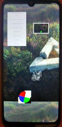
Weston on downstream kernel
-
Lavender booting mainline
Additional info
Partition list
Partition list
Android Verified Boot (vbmeta)
This device is using Android_Verified_Boot_(AVB) so, if you did not flash any custom Android ROM, you may need to flash vbmeta partition with vbmeta.img with verification disabled flag. pmbootstrap now can generate such image nad flash it with one command:
$ pmbootstrap flasher flash_vbmeta
DTBO partition
This device is using a dedicated partition to store the Device Tree Blob Overlay. Read more at https://source.android.com/devices/architecture/dto/partitions . We need to find a way to flash generated dt.img to dtbo partition during installation process. (add pmbootstrap flasher flash_dtbo?)
Update: looks like dtbo partition is not used during boot by LineageOS's kernel, because it is using appended DTB (CONFIG_BUILD_ARM64_APPENDED_DTB_IMAGE=y)
Update2: device tree from dtbo partition can still be used by bootloader? Yes, it is. bootloader tries to actually overlay dtb from dtbo partition over a dtb found in boot.img, and if it fails to do so, it falls back into fastboot mode. Example bootloader debug UART output in that case:
Memory Base Address: 0x40000000
Decompressing kernel image start: 2700 ms
Decompressing kernel image done: 2852 ms
ufdt apply overlay failed
Launching fastboot
See Zhuowei's notes on creating custom dtbo partition: https://gitlab.com/zhuowei/dtbo-google-crosshatch-mainline
For mainline kernel just fastboot erase dtbo works. Example output when dtbo partition is erased:
Memory Base Address: 0x40000000
Decompressing kernel image start: 2641 ms
Decompressing kernel image done: 2793 ms
Dtbo hdr magic mismatch 0, with D7B7AB1E
Best match DTB tags 317/00020008/0x00000000/0/1001B/102001A/0/0/(offset)0x97128304/(size)0x00000653
Using pmic info 0x1001B/0x102001A/0x0/0x0 for device 0x2001B/0x102001A/0x0/0x0
Memory Base Address: 0x40000000
smem protocol = 9C2FA0A0
board_id1 is 1
 board_id2 is 1
 board_id3 is 0
board_id is 1
get_boardid_from_smem,SUCCESS ,board_id=0x102,cpu_id=0x39148C8C,hwdefined=0
 PON Reason is 17 cold_boot:1 charger path: 1
...(proceeding to normal boot procedure)...
Bootloader cmdline
Stock bootloader is doing nasty things with kernel command line: it passes a lot of arguments that make booting custom OS (like postmarketOS) impossible
Full list of stock command line parameters:
ramoops_memreserve=4M comes from defconfig, next from boot.img, others (starting with first androidboot. and below) come from bootloader directly.
Harmful kernel command line params from bootloader
Options like root=, skip_initramfs make kernel look for a specific partition to mount at /, skipping initramfs, which is incompatible with default booting methods of postmarketOS. That's why some tricky patches are needed, similar to ones used by Zhuowei in Google Pixel port: 1, 2.
Another hack to fix bootloader cmdline params by opendata26: init: ignore bootloader cmdline params for mounts
Some info on skip_initramfs kernel cmdline parameter: https://forum.xda-developers.com/apps/magisk/pixel-2-pixel-2-xl-support-t3697427/post74361728#post74361728
Way to get boot log
This device known to ship with the oem getlog fastboot command.
This is not a trivial command to use, but it is extremely useful as it allows side-stepping the need to boot in a known working system to use the ramoops console. The output of the command is a jumble, but is still usable for figuring out early boot issues. It is much better than having to rely on a booted system to get the information, but still not as good as having a dedicated serial access.
Example usage follows.
$ fastboot oem getlog 2>&1
(bootloader) [    0.000000] Booting Linux on physical CPU 0x0
[    0.000
(bootloader) 000] Initializing cgroup subsys cpuset
[    0.000000] Initi
(bootloader) alizing cgroup subsys cpu
[    0.000000] Initializing cgrou
(bootloader) p subsys cpuacct
[    0.000000] Initializing cgroup subsys
(bootloader) schedtune
[    0.000000] Linux version 4.4.153 (nixbld@loca
(bootloader) lhost) (gcc version 4.9.4 (GCC) ) #2 SMP PREEMPT Sat Nov 23
(bootloader)  20:31:33 UTC 2019
[    0.000000] Boot CPU: AArch64 Process
(bootloader) or [51af8014]
[...]
As the output of the command is on stderr, here's how to output to a file.
$ fastboot oem getlog > log.txt 2>&1
It is unknown if there are ways to make the output better. (Apply some kind error correction algorithm?)
EDIT: seems to not work for me, whatever you do, the output is:
$ fastboot oem getlog
                                                  (bootloader) [Macle]Maybe no last kmsg
OKAY [  0.000s]
Finished. Total time: 0.000s
Probably needs a crash? But I can read pstore-console (dmesg) logs from booted TWRP recovery fine..

Getting logs through debug UART
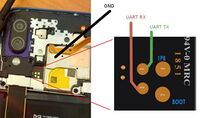
You have to disassemble the phone (just removing back cover is enough). You'll have to heat up edges of the back cover (as shown in disassembling video, see Links below) before trying to remove it. Be careful! It is made of glass! Also be careful about fingerprint sensor connector, it is connected to a back cover you are trying to remove. Don't rip it.
In the center you will see 4 test points that are available. (See the picture) Two bigger ones (0.8mm) are EDL (FORCE_USB_BOOT) pins. UART test points are two smaller ones on the left (0.5mm). TP11 is UART TX (gpio 4), TP10 is UART RX (gpio 5). GND is that whole metal shielding, that covers the center of the board. So, to get debug logs from UART it is enough to connect UART TX from the board to RX pin on the converter, and connect GND between phone and GND pin on the converter.
Links
- Current pmaports development branch
- Current mainline kernel development branch
- Mainline development
- NixOS-mobile lavender MR
- https://www.youtube.com/watch?v=6GqXqW2Nygc Disassembling video (Rus)
- https://www.anandtech.com/show/11338/qualcomm-announces-snapdragon-660-630-mobile-platforms
- List of mobile phones on SDM660 SoC

