PINE64 PinePhone (pine64-pinephone)
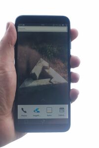
 A PinePhone with a case | |
| Manufacturer | PINE64 |
|---|---|
| Name | PinePhone |
| Codename | pine64-pinephone |
| Released | 2019 |
| Hardware | |
| Chipset | Allwinner A64 |
| CPU | 4x 1152 MHz Cortex-A53 |
| GPU | Mali 400 |
| Memory | 2 GB |
| Architecture | aarch64 |
| Software | |
| Original software | Linux 5.3.0 |
| postmarketOS | |
| Category | testing |
| Pre-built images | no |
| Mainline | yes |
| USB Networking |
Works |
|---|---|
| Internal storage |
No data |
| SD card |
No data |
| Battery |
Works |
| Screen |
Works |
| Touchscreen |
Works |
| Multimedia | |
| 3D Acceleration |
Works |
| Audio |
Works |
| Camera |
Partial |
| Camera Flash |
No data |
| Connectivity | |
| WiFi |
Works |
| Bluetooth |
Partial |
| GPS |
Works |
| NFC |
No data |
| Modem | |
| Calls |
Partial |
| SMS |
Partial |
| Mobile data |
Works |
| Miscellaneous | |
| FDE |
Broken |
| USB OTG |
Broken |
| HDMI/DP |
No data |
| Sensors | |
| Accelerometer |
Works |
| Magnetometer |
No data |
| Ambient Light |
No data |
| Proximity |
No data |
| Hall Effect |
No data |
| Haptics |
No data |
| Barometer |
No data |
The PinePhone is a smartphone by PINE64. The postmarketOS vendor and device names are "pine64" and "pinephone" respectively. The back panel can be lifted off by pulling at the notch on the bottom-left corner of the phone. This exposes the battery, microSD and SIM slots, and dipswitches. It comes with a 3000mAh battery and uses the same form-factor as the Samsung J7 for replacement.
Contributors
Installation
The recommended installation procedure is installing to a microSD card by passing --sdcard=/dev/... to pmbootstrap install. The pinephone will boot to the microSD card first if it's bootable, or the eMMC if not. postmarketOS may be installed onto the eMMC by running pmbootstrap install --sdcard=/dev/mmcblk... from a Linux distribution booted via the microSD card.
Serial console
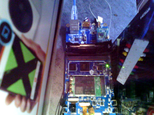
The PinePhone has a serial port in the headphone connector, it's activated by the 6th contact on the dipswitch. If the switch is on then the headphone connector is in audio mode, if it's off then it's in UART mode.
The uart is 115200n8
The pinout for the serial connector on the tablet side is:
- Tip: RX
- Ring: TX
- Sleeve: GND
The serial connection is 3.3V
You can also buy the debug cable from PINE64 Store
Hardware switches
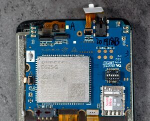
There's a 6 contact dipswitch on the back of the phone underneath the back cover. The 6 switches are for enableing/disableing hardware components. The switch has tiny numbers 1-6 beneath the contacts, moving the contact up sets that contact on.
| # | Off | On |
|---|---|---|
| 1 | Modem disabled | Modem enabled |
| 2 | Wifi/BT disabled | Wifi/BT enabled |
| 3 | Microphone disabled | Microphone enabled |
| 4 | Rear camera disabled | Rear camera enabled |
| 5 | Front camera disabled | Front camera enabled |
| 6 | Headphone UART mode | Headphone audio mode |
Expansion port
There is a 2x3 grid of pogo pins on the back of the pinephone for connecting a back cover with extra hardware like an extended battery case or a keyboard case. The pinout for this connector:
| Interrupt | I2C | I2C |
| 3v3 | usb 5v | gnd |
the USB5v line is meant to charge the phone and the 3v3 is to power peripherals to the phone. The I2C and interrupt lines have pull-ups on the phone side.
Components
| Component | Model | Driver |
|---|---|---|
| Touchscreen | Goodix | TOUCHSCREEN_GOODIX |
| Rear camera | OmniVision OV5640 | VIDEO_OV5640 |
| Camera flash | SGMICRO SGM3140 | LEDS_SGM3140 |
| Front camera | GalaxyCore GC2145 | Nope |
| LCD | Xingbangda XBD599 | CONFIG_DRM_PANEL_XINGBANGDA_XBD599 |
| WiFi | Realtek RTL8723CS | RTL8723CS |
| Bluetooth | Realtek RTL8723CS | BT_HCIUART_RTL |
| Modem | Quectel EC25-E | USB_NET_QMI_WWAN |
| GNSS/GPS | Quectel EC25-G | CONFIG_USB_SERIAL_OPTION |
| Magnetometer | ST LIS3MDL | IIO_ST_MAGN_3AXIS |
| Ambient light / Proximity | SensorTek STK3335 | STK3310 |
| Sixaxis | InvenSense MPU-6050 | INV_MPU6050_I2C |
| Vibration motor | ? | INPUT_GPIO_VIBRA |
| Notification LED | LED0603RGB | LEDS_GPIO |
| Volume buttons | Buttons connected to the KEYADC | KEYBOARD_SUN4I_LRADC |
| Power button | X-Powers AXP803 | INPUT_AXP20X_PEK |
| Battery fuel gauge | X-Powers AXP803 | BATTERY_AXP20X |
Cameras
The camera's both share the csi-0 bus. Currently only the rear camera (OV5640) has mainline linux support.
It's also not clear how the camera switching would work on the software side, the current issue is that the sunxi csi driver doesn't support multiple camera endpoints.
The camera hardware pipeline is controlled with /dev/media1 and media-ctl, the result is on /dev/video1
pine-dontbeevil:~# media-ctl -d /dev/media1 --set-v4l2 '"ov5640 2-003c":0[fmt:UYVY8_2X8/1280x720]'
pine-dontbeevil:~# ffmpeg -s 1280x720 -f video4linux2 -i /dev/video0 -vframes 1 selfie.jpg
Camera Flash
The camera flash consist out of a SG Micro SGM3140 "500mA Buck/Boost Charge Pump LED Driver" and a EHP-C04 LED.
The driver supports Flash and Torch mode, the first being brighter but only for about 300ms, when it switches to Torch mode. Torch mode is lower brightness but can be turned on continuously.
# Turn on Flash, wait 0.3s, turn off
echo 1 > /sys/class/leds/sgm3140-flash/flash_strobe
sleep 0.3
echo 0 > /sys/class/leds/sgm3140-flash/flash_strobe
# Turn on Torch
echo 1 > /sys/class/leds/sgm3140-flash/brightness
# Turn off Torch
echo 0 > /sys/class/leds/sgm3140-flash/flash_strobe
WiFi
?
Bluetooth
There is a patch series on lkml. A v2 for this series is in progress.
Modem
Receiving text messages works. Calls should work too but weren't tested yet.
Sensors
All sensors work and are accessible as Industrial I/O (iio) devices in linux. To query the data you can cat the files in `/sys/bus/iio/` to make the kernel module query the sensors
dontbeevil:~# cat /sys/bus/iio/devices/iio\:device0/name
mpu6050
dontbeevil:~# cat /sys/bus/iio/devices/iio\:device0/in_accel_z_raw
-17594
dontbeevil:~# echo "Verified gravity still exists"
RGB Led
# Activate LED
echo 1 > /sys/class/leds/$COLOR/brightness
# Deactivate LED
echo 0 > /sys/class/leds/$COLOR/brightness
Audio
Speakers
Sound output should work after unmuting AIF1 Slot 0 digital
See also
- pmaports!308 Initial merge request

