Samsung Galaxy A5 2017 (samsung-a5y17lte): Difference between revisions
Dsankouski (talk | contribs) No edit summary |
m Add type |
||
| (38 intermediate revisions by 9 users not shown) | |||
| Line 1: | Line 1: | ||
{{Infobox device | {{Infobox device | ||
| manufacturer = Samsung | | manufacturer = Samsung | ||
| name = | | name = Galaxy A5 (2017) | ||
| codename = samsung-a5y17lte | | codename = samsung-a5y17lte | ||
| image = File:a5y17lte_pmos.jpg | | image = File:a5y17lte_pmos.jpg | ||
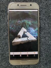
| imagecaption = Samsung Galaxy A5 | | imagecaption = Samsung Galaxy A5 | ||
| releaseyear = 2017 | | releaseyear = 2017 | ||
| originalsoftware = Android 6 | | originalsoftware = Android | ||
| chipset = Exynos 7880 | | originalversion = 6.0.1 | ||
| cpu = | | extendedversion = 8.0 | ||
| gpu = | | chipset = Samsung Exynos 7880 | ||
| storage = | | cpu = 8x 1.9 GHz Cortex-A53 | ||
| display = | | gpu = Mali-T830 MP3 | ||
| memory = | | storage = 32 GB | ||
| display = 1080x1920 Super AMOLED | |||
| memory = 3 GB | |||
| architecture = aarch64 | | architecture = aarch64 | ||
| type = handset | |||
| pmoskernel = 3.18.14 | |||
<!-- the following status_* questions should be answered with Y - yes, P - partial, N - no, or left blank (for untested or unknown) --> | <!-- the following status_* questions should be answered with Y - yes, P - partial, N - no, or left blank (for untested or unknown) --> | ||
| status_usbnet = Y | | status_usbnet = Y | ||
| status_flashing = N | | status_flashing = N | ||
| status_touch = | | status_touch = Y | ||
| status_screen = Y | | status_screen = Y | ||
| status_wifi = Y | | status_wifi = Y | ||
| Line 36: | Line 40: | ||
| booting = yes <!-- The device is booting at all, can be yes/no *IMPORTANT* --> | | booting = yes <!-- The device is booting at all, can be yes/no *IMPORTANT* --> | ||
| status_otg = Y | | status_otg = Y | ||
| whet_dhry = 1691.5 | |||
| whet_dhry = | |||
}} | }} | ||
| Line 56: | Line 52: | ||
== Users owning this device == | == Users owning this device == | ||
{{Device owners}} | {{Device owners}} | ||
== How to enter flash mode == | == How to enter flash mode == | ||
| Line 78: | Line 70: | ||
=== USB === | === USB === | ||
Device is equipped with usb type-c receptacle. No UART cable schematic available as of 04.01.2020. Available info: | Device is equipped with usb type-c receptacle. No UART JIG mode cable schematic available as of 04.01.2020. However, it is possible to use chainloaded u-boot to get uart on usb. See [https://github.com/dsankouski/u-boot/tree/a5y17lte/board/samsung/axy17lte u-boot port readme for instructions] | ||
Available MUIC info: | |||
* The receptacle is managed by s2mu004 kernel module. Module is capable to manage non type-c receptacles (see CONFIG_MUIC_S2MU004_NON_USB_C_TYPE option) | * The receptacle is managed by s2mu004 kernel module. Module is capable to manage non type-c receptacles (see CONFIG_MUIC_S2MU004_NON_USB_C_TYPE option) | ||
* Receptacle has non standard pinout: B12 (considering, A row facing top, B row facing bottom side of the phone) pin is not connected to the ground. | * Receptacle has non standard pinout: B12 (considering, A row facing top, B row facing bottom side of the phone) pin is not connected to the ground. | ||
* Device can detect water in usb receptacle, by measuring resistance between B12 pin. | * Device can detect water in usb receptacle, by measuring resistance between B12 pin and ground. | ||
* Attaching 619K resistor to B12 pin results in ADC_JIG_UART_ON value in ADC register, during water detection sequence | * Device can detect plug attach, with ALL pins unconnected, including GND and VBUS pins. How? | ||
* Enter UART mode by attaching resistors | * Attaching 619K resistor to B12 pin results in ADC_JIG_UART_ON value in ADC register, during water detection sequence. | ||
* UART mode detection most likely is implemented in muic firmware. | * Enter UART mode by attaching resistors should be possible in NON type-c mode. (file s2mu004-muic.c ,lines 2835,2797) | ||
* Device has no USB type-c debug accessory mode(tried both with rd/rd and rp/rp resistors) | |||
* UART mode detection most likely is implemented in muic firmware, if exists, or chip logic. | |||
Open questions: | Open questions: | ||
* How device can detect plug attach, when ALL plug pins are unconnected. | * How device can detect plug attach, when ALL plug pins are unconnected. | ||
* How device detects UART debug cable attach? | * How device detects UART debug cable attach? | ||
Muic driver sysfs attributes are in <code>/sys/devices/virtual/sec/switch</code> folder | |||
=== Wlan === | === Wlan === | ||
wifi module gets initialized after 180 seconds. This is due to missing firmware files, and 60 secs timeout. | wifi module gets initialized after 180 seconds. This is due to missing firmware files, and 60 secs timeout. | ||
To connect, use wpa_supplicant: | |||
==== Create wpa supplicant config ==== | |||
/etc/wpa_supplicant/wpa_supplicant.conf | |||
ctrl_interface=/run/wpa_supplicant | |||
update_config=1 | |||
==== Add wlan access point authentication ==== | |||
wpa_passphrase <access point> <password> >> /etc/wpa_supplicant/wpa_supplicant.conf | |||
==== Launch wpa supplicant ==== | |||
sudo wpa_supplicant -B -i wlan0 -c /etc/wpa_supplicant/wpa_supplicant.conf | |||
sudo dhclient wlan0 | |||
=== UART cable === | |||
<span style="color:red">'''Attention:''' Author is not responsible for any damage to your devices. Signal level is 1.8V. You may fry your board, using standard 3.3V - 5V UART. | |||
</span> | |||
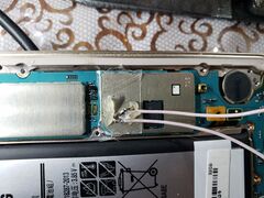
It is possible to connect to UART port(/dev/ttySAC2) on the mainboard. It is located on [https://wiki.postmarketos.org/wiki/File:A5y17lte_test_port.jpg pins 1(RX), 2(TX)] of the test port, and used by bootloader to log loading process. | |||
==== Bill of materials ==== | |||
* Adhesive tape | |||
* Precise soldering equipment | |||
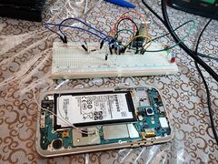
* USB - UART converter (you need also level shifter, if converter does not support 1.8V signals. I used [https://electronics.stackexchange.com/questions/333229/1-8v-uart-with-3-3v-uart schematic on two transistors]) | |||
* Breadboard | |||
* Wires | |||
* Thermal glue | |||
<gallery caption="Assembly photos" widths="240px" heights="180px"> | |||
File:A5y17lte uart wires.jpg|Wires, soldered to UART port. | |||
File:A5y17lte uart assembly.jpg|a5y17lte, connected to USB - UART converter via level shifter. | |||
</gallery> | |||
==== Enabling console output ==== | |||
===== Downstream kernel ===== | |||
* Build kernel with options: | |||
**CONFIG_CMDLINE="earlycon=exynos,0x13820000,115200n8 console=ttySAC2,115200" | |||
**CONFIG_CMDLINE_EXTEND=y | |||
* Optional (enable login console on ttySAC2)[https://wiki.alpinelinux.org/wiki/Enable_Serial_Console_on_Boot]: | |||
=== UART USB-debug cable schematic === | |||
Currently there's no automatic way to switch MUIC on debug uart. It may be done with u-boot custom port. | |||
<code> | |||
Phone--------------------------------------PC | |||
USB type-c---------------------------------UART adapter | |||
A6 (D+, Rx)--------------------------------Tx | |||
A7 (D-, Tx)--------------------------------Rx | |||
A1 and / or (B1) --------------------------GND | |||
A4 and / or (A9, B4, B9)-------------------5V charging | |||
</code> | |||
=== Main board === | |||
<gallery> | |||
File:A5y17lte test port.jpg|Test port pin numbering | |||
</gallery> | |||
=== Mainlining === | |||
==== Exynos calibration table driver (ect_parser.c) ==== | |||
Exynos calibration table driver - simple driver, that reads and parses predefined cpu address range. It has voltage, cpu, gpu frequency tables, and more. | |||
Legacy driver uses __raw_read macro to access data. | |||
Calibration table resides in volatile cpu address region (probably loaded there by bootloader into RAM?). One can write to ect cpu address region | |||
=== U-boot === | |||
Has support in main tree. | |||
See also [https://u-boot.readthedocs.io/en/latest/board/samsung/axy17lte.html u-boot docs ] | |||
== Hardware == | |||
{|class="wikitable feature-colors" | |||
! Component !! Model !! Notes | |||
|- | |||
| Flash || Samsung BJTD4R || 32GB | |||
|- | |||
| Charging || Samsung s2mu004 || | |||
|- | |||
| Touchscreen || Zinitix BT532 || | |||
|- | |||
| Touchkeys || Abov FT1804 || | |||
|- | |||
| Gyroscope/Accelerometer || STMicroelectronics K6DS3TR || | |||
|- | |||
| Light/Proximity sensor || ams TMD3725 || | |||
|- | |||
| Magnetometer || AKM (Asahi Kasei Microdevices) AK09916C || | |||
|- | |||
| Barometer || STMicroelectronics LPS25H || | |||
|- | |||
| FM Radio || Silicon Labs si47xx || | |||
|- | |||
| Wi-Fi/Bluetooth || Qualcomm Atheros ar6k || Exact model unknown, could be one from [https://github.com/LineageOS/android_kernel_samsung_universal7880/blob/80707d1/drivers/net/wireless/qcacld-2.0/CORE/SERVICES/HIF/sdio/linux/native_sdio/src/hif.c#L176-L223 this] table | |||
|- | |||
| Fingerprint || EgisTec ET5XX || Connected via SPI | |||
|- | |||
| Rear camera || Samsung S5K3P8 || Phone reports "s5k3p8sx" as front camera | |||
|- | |||
| Lens actuator || [https://github.com/LineageOS/android_kernel_samsung_universal7880/blob/80707d1/arch/arm64/boot/dts/exynos7880-a5y17lte_common.dtsi#L513 (Samsung?)] AK7372 || | |||
|} | |||
== See also == | == See also == | ||
* [https://github.com/dsankouski/u-boot/tree/a5y17lte/board/samsung/axy17lte U-boot port] | |||
* {{Device package|samsung-a5y17lte}} | |||
* | * {{Kernel package|samsung-a5y17lte}} | ||
* | |||
* | |||
Revision as of 22:39, 12 September 2024
 Samsung Galaxy A5 | |
| Manufacturer | Samsung |
|---|---|
| Name | Galaxy A5 (2017) |
| Codename | samsung-a5y17lte |
| Released | 2017 |
| Type | handset |
| Hardware | |
| Chipset | Samsung Exynos 7880 |
| CPU | 8x 1.9 GHz Cortex-A53 |
| GPU | Mali-T830 MP3 |
| Display | 1080x1920 Super AMOLED |
| Storage | 32 GB |
| Memory | 3 GB |
| Architecture | aarch64 |
| Software | |
| Original software | Android |
| Original version | 6.0.1 |
| Extended version | 8.0 |
| postmarketOS | |
| Category | testing |
| Pre-built images | no |
| Mainline | no |
| postmarketOS kernel | 3.18.14 |
| Unixbench Whet/Dhry score | 1691.5 |
| Flashing |
Broken |
|---|---|
| USB Networking |
Works |
| Internal storage |
No data |
| SD card |
No data |
| Battery |
Works |
| Screen |
Works |
| Touchscreen |
Works |
| Multimedia | |
| 3D Acceleration |
No data |
| Audio |
No data |
| Camera |
No data |
| Camera Flash |
No data |
| Connectivity | |
| WiFi |
Works |
| Bluetooth |
No data |
| GPS |
No data |
| NFC |
No data |
| Modem | |
| Calls |
No data |
| SMS |
No data |
| Mobile data |
No data |
| Miscellaneous | |
| FDE |
No data |
| USB OTG |
Works |
| HDMI/DP |
No data |
| Sensors | |
| Accelerometer |
No data |
| Magnetometer |
No data |
| Ambient Light |
No data |
| Proximity |
No data |
| Hall Effect |
No data |
| Haptics |
No data |
| Barometer |
No data |
Contributors
- dsankouski
Maintainer(s)
Users owning this device
- Bastindo (Notes: very good condition, running Lineage 20)
- Danfigasystems (Notes: 16GB model)
- Dsankouski
- Keith. (Notes: Needs a new battery)
- KQuote03
- LegoLivesMatter (Notes: Dead screen, possibly the display cable just got disconnected?)
- Manty (Notes: Android development)
- SuperPou (Notes: Broken screen, touch works though)
How to enter flash mode
When the device is fully powered off, hold Power, Volume Down and Home for a few seconds.
A (turquoise) download mode warning screen should appear, press Volume Up to confirm.
Installation
It is recommended to sideload an android recovery zip through TWRP for the easiest process, since heimdall freaks out about the subpartitions in SYSTEM and won't move past ~7%.
You can use pmbootstrap flasher flash_kernel and then use netcat or similar to flash SYSTEM, but this is a longer and more redundant method.
$ pmbootstrap install --android-recovery-zip
$ pmbootstrap flasher --method=adb sideload
Notes
USB
Device is equipped with usb type-c receptacle. No UART JIG mode cable schematic available as of 04.01.2020. However, it is possible to use chainloaded u-boot to get uart on usb. See u-boot port readme for instructions
Available MUIC info:
- The receptacle is managed by s2mu004 kernel module. Module is capable to manage non type-c receptacles (see CONFIG_MUIC_S2MU004_NON_USB_C_TYPE option)
- Receptacle has non standard pinout: B12 (considering, A row facing top, B row facing bottom side of the phone) pin is not connected to the ground.
- Device can detect water in usb receptacle, by measuring resistance between B12 pin and ground.
- Device can detect plug attach, with ALL pins unconnected, including GND and VBUS pins. How?
- Attaching 619K resistor to B12 pin results in ADC_JIG_UART_ON value in ADC register, during water detection sequence.
- Enter UART mode by attaching resistors should be possible in NON type-c mode. (file s2mu004-muic.c ,lines 2835,2797)
- Device has no USB type-c debug accessory mode(tried both with rd/rd and rp/rp resistors)
- UART mode detection most likely is implemented in muic firmware, if exists, or chip logic.
Open questions:
- How device can detect plug attach, when ALL plug pins are unconnected.
- How device detects UART debug cable attach?
Muic driver sysfs attributes are in /sys/devices/virtual/sec/switch folder
Wlan
wifi module gets initialized after 180 seconds. This is due to missing firmware files, and 60 secs timeout.
To connect, use wpa_supplicant:
Create wpa supplicant config
/etc/wpa_supplicant/wpa_supplicant.conf
ctrl_interface=/run/wpa_supplicant
update_config=1
Add wlan access point authentication
wpa_passphrase <access point> <password> >> /etc/wpa_supplicant/wpa_supplicant.conf
Launch wpa supplicant
sudo wpa_supplicant -B -i wlan0 -c /etc/wpa_supplicant/wpa_supplicant.conf
sudo dhclient wlan0
UART cable
Attention: Author is not responsible for any damage to your devices. Signal level is 1.8V. You may fry your board, using standard 3.3V - 5V UART.
It is possible to connect to UART port(/dev/ttySAC2) on the mainboard. It is located on pins 1(RX), 2(TX) of the test port, and used by bootloader to log loading process.
Bill of materials
- Adhesive tape
- Precise soldering equipment
- USB - UART converter (you need also level shifter, if converter does not support 1.8V signals. I used schematic on two transistors)
- Breadboard
- Wires
- Thermal glue
- Assembly photos
-
Wires, soldered to UART port.
-
a5y17lte, connected to USB - UART converter via level shifter.
Enabling console output
Downstream kernel
- Build kernel with options:
- CONFIG_CMDLINE="earlycon=exynos,0x13820000,115200n8 console=ttySAC2,115200"
- CONFIG_CMDLINE_EXTEND=y
- Optional (enable login console on ttySAC2)[1]:
UART USB-debug cable schematic
Currently there's no automatic way to switch MUIC on debug uart. It may be done with u-boot custom port.
Phone--------------------------------------PC
USB type-c---------------------------------UART adapter
A6 (D+, Rx)--------------------------------Tx
A7 (D-, Tx)--------------------------------Rx
A1 and / or (B1) --------------------------GND
A4 and / or (A9, B4, B9)-------------------5V charging
Main board
-
Test port pin numbering
Mainlining
Exynos calibration table driver (ect_parser.c)
Exynos calibration table driver - simple driver, that reads and parses predefined cpu address range. It has voltage, cpu, gpu frequency tables, and more.
Legacy driver uses __raw_read macro to access data. Calibration table resides in volatile cpu address region (probably loaded there by bootloader into RAM?). One can write to ect cpu address region
U-boot
Has support in main tree. See also u-boot docs
Hardware
| Component | Model | Notes |
|---|---|---|
| Flash | Samsung BJTD4R | 32GB |
| Charging | Samsung s2mu004 | |
| Touchscreen | Zinitix BT532 | |
| Touchkeys | Abov FT1804 | |
| Gyroscope/Accelerometer | STMicroelectronics K6DS3TR | |
| Light/Proximity sensor | ams TMD3725 | |
| Magnetometer | AKM (Asahi Kasei Microdevices) AK09916C | |
| Barometer | STMicroelectronics LPS25H | |
| FM Radio | Silicon Labs si47xx | |
| Wi-Fi/Bluetooth | Qualcomm Atheros ar6k | Exact model unknown, could be one from this table |
| Fingerprint | EgisTec ET5XX | Connected via SPI |
| Rear camera | Samsung S5K3P8 | Phone reports "s5k3p8sx" as front camera |
| Lens actuator | (Samsung?) AK7372 |


