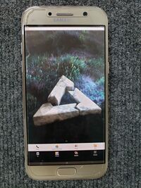
Samsung Galaxy A5 2017 (samsung-a5y17lte): Difference between revisions
mNo edit summary |
Dsankouski (talk | contribs) Arrange photos in a gallery |
||
| Line 104: | Line 104: | ||
</span> | </span> | ||
It is possible to connect to UART port(/dev/ttySAC2) on the mainboard. It is located on pins 1(RX), 2(TX) of the test port, and used by bootloader to log loading process. | It is possible to connect to UART port(/dev/ttySAC2) on the mainboard. It is located on [https://wiki.postmarketos.org/wiki/File:A5y17lte_test_port.jpg pins 1(RX), 2(TX)] of the test port, and used by bootloader to log loading process. | ||
==== Bill of materials ==== | ==== Bill of materials ==== | ||
| Line 115: | Line 115: | ||
<gallery caption="Assembly photos" widths="240px" heights="180px"> | |||
File:A5y17lte uart wires.jpg|Wires, soldered to UART port. | |||
File:A5y17lte uart assembly.jpg|a5y17lte, connected to USB - UART converter via level shifter. | |||
</gallery> | |||
=== | === Main board === | ||
<gallery> | |||
File:A5y17lte test port.jpg|Test port pin numbering | |||
</gallery> | |||
== See also == | == See also == | ||
Revision as of 15:11, 1 April 2020
 Samsung Galaxy A5 | |
| Manufacturer | Samsung |
|---|---|
| Name | Galaxy A5 (2017) |
| Codename | samsung-a5y17lte |
| Released | 2017 |
| Hardware | |
| Chipset | Exynos 7880 |
| CPU | 8x 1.9 GHz Cortex-A53 |
| GPU | Mali-T830 MP3 |
| Display | 5.2 inch 16:9, 1920 x 1080 pixel 424 PPI, capacitive, Super AMOLED, Corning Gorilla Glass 5, glossy: yes |
| Storage | 32 GB |
| Memory | 3 GB |
| Architecture | aarch64 |
| Software | |
| Original software | Android 6.0.1 - 8.0 |
| postmarketOS | |
| Category | testing |
| Pre-built images | no |
| Mainline | no |
| postmarketOS kernel | 3.18.14 |
| Unixbench Whet/Dhry score | 1691.5 |
| Flashing |
Broken |
|---|---|
| USB Networking |
Works |
| Internal storage |
No data |
| SD card |
No data |
| Battery |
Works |
| Screen |
Works |
| Touchscreen |
Works |
| Multimedia | |
| 3D Acceleration |
No data |
| Audio |
No data |
| Camera |
No data |
| Camera Flash |
No data |
| Connectivity | |
| WiFi |
Works |
| Bluetooth |
No data |
| GPS |
No data |
| NFC |
No data |
| Modem | |
| Calls |
No data |
| SMS |
No data |
| Mobile data |
No data |
| Miscellaneous | |
| FDE |
No data |
| USB OTG |
Works |
| HDMI/DP |
No data |
| Sensors | |
| Accelerometer |
No data |
| Magnetometer |
No data |
| Ambient Light |
No data |
| Proximity |
No data |
| Hall Effect |
No data |
| Haptics |
No data |
| Barometer |
No data |
Contributors
- dsankouski
Maintainer(s)
Users owning this device
- Bastindo (Notes: very good condition, running Lineage 20)
- Danfigasystems (Notes: 16GB model)
- Dsankouski
- Keith. (Notes: Needs a new battery)
- KQuote03
- LegoLivesMatter (Notes: Dead screen, possibly the display cable just got disconnected?)
- Manty (Notes: Android development)
- SuperPou (Notes: Broken screen, touch works though)
How to enter flash mode
When the device is fully powered off, hold Power, Volume Down and Home for a few seconds.
A (turquoise) download mode warning screen should appear, press Volume Up to confirm.
Installation
It is recommended to sideload an android recovery zip through TWRP for the easiest process, since heimdall freaks out about the subpartitions in SYSTEM and won't move past ~7%.
You can use pmbootstrap flasher flash_kernel and then use netcat or similar to flash SYSTEM, but this is a longer and more redundant method.
$ pmbootstrap install --android-recovery-zip
$ pmbootstrap flasher --method=adb sideload
Notes
USB
Device is equipped with usb type-c receptacle. No UART JIG mode cable schematic available as of 04.01.2020. Available info:
- The receptacle is managed by s2mu004 kernel module. Module is capable to manage non type-c receptacles (see CONFIG_MUIC_S2MU004_NON_USB_C_TYPE option)
- Receptacle has non standard pinout: B12 (considering, A row facing top, B row facing bottom side of the phone) pin is not connected to the ground.
- Device can detect water in usb receptacle, by measuring resistance between B12 pin.
- Device can detect plug attach, with ALL pins unconnected, including GND and VBUS pins. How?
- Attaching 619K resistor to B12 pin results in ADC_JIG_UART_ON value in ADC register, during water detection sequence.
- Enter UART mode by attaching resistors should be possible in NON type-c mode. (file s2mu004-muic.c ,lines 2835,2797)
- Device has no USB type-c debug accessory mode(tried both with rd/rd and rp/rp resistors)
- UART mode detection most likely is implemented in muic firmware, if exists, or chip logic.
Open questions:
- How device can detect plug attach, when ALL plug pins are unconnected.
- How device detects UART debug cable attach?
Wlan
wifi module gets initialized after 180 seconds. This is due to missing firmware files, and 60 secs timeout.
UART cable
Attention: Author is not responsible for any damage to your devices. Signal level is 1.8V. You may fry your board, using standard 3.3V - 5V UART.
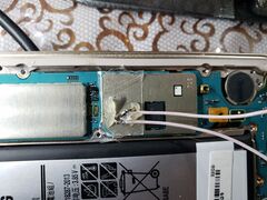
It is possible to connect to UART port(/dev/ttySAC2) on the mainboard. It is located on pins 1(RX), 2(TX) of the test port, and used by bootloader to log loading process.
Bill of materials
- Adhesive tape
- Precise soldering equipment
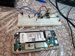
- USB - UART converter (you need also level shifter, if converter does not support 1.8V signals. I used schematic on two transistors)
- Breadboard
- Wires
- Thermal glue
- Assembly photos
-
Wires, soldered to UART port.
-
a5y17lte, connected to USB - UART converter via level shifter.
Main board
-
Test port pin numbering


